
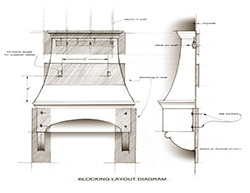
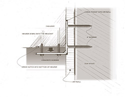
 Once you have successfully cast your parts and finished them completely, you are ready to install your hood. You have already supplied the contractor with the proper drawings specifying where to place blocking (like the drawings at the top of this page), the vent location is established, and any and all brackets have been installed prior to closing the wall if so specified.
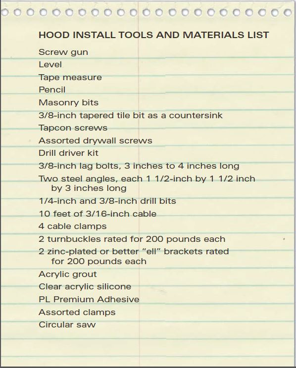
Use the Tools & Materials list (facing page) to assemble what you’ll need.
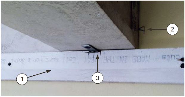 The first step is to mark the height of the unit on the wall using the counters from your approved shop drawings. Mark the center of the hood and screw a cleat (1) to the wall to temporarily hold the header in place. Also, mark the outside edges (2) since you will not be able to locate the center once you place the header. Next, an L (3) bracket will be screwed into the wall to carry the weight of the unit and keep it in place while the next tasks are performed. The whole area behind the header should have been blocked as per your drawing to allow for freedom in fastening the header wherever it may be necessary. The L bracket will be set in the center of where the support brackets will be placed. The brackets will be supported by the header, so it is important to make sure the header is securely fastened.
 The L bracket can be recessed into the wall behind the header or ground into the header so the header sits flat against the wall. In the same respect the bracket below can be ground to accommodate the thickness of the L bracket and/or the Tapcon screw heads. Two heavy No. 10 or better wood or sheet metal screws, pan-head or flat-head, can be used to screw the L bracket into the blocking. The size that is required only has to overcome the possible force of the header’s weight.
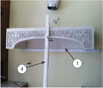 You will need to clamp a board or stud (4) to the front of the header to level it and carry the load until the unit can be bolted in place. Precut your board and get a clamp ready to hold the header stable while you screw the L bracket into the header.
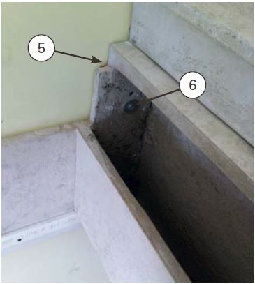 Once you level the header from front to back and it is level from left to right on the cleat (1), you can bolt (6) the header into the blocking from inside the left and right cavities of the header, where the bolts are not visible and the header is strongest. You may also use mastic to set the back of the header securely to the wall. When you drill the hole through the header, 1/2-inch, and then predrill the blocking for the lag bolt (6), you are ready to install and tighten the lag bolt. Be sure to shim (5) the space between the header and the wall if there is a gap so that you do not change the position of the header as you tighten it, and keep the shims close to the bolt so that when it is tight you do not crack or damage the header. DO NOT overtighten.
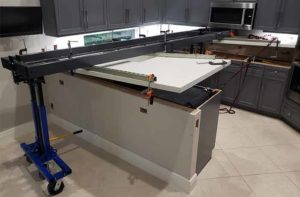
 This is the base you will work from. Every item from here will only be as level and straight as you have made this part.
The next step is to place the top molding (7) section, which will be in one piece. First dry-fit the molding on the hood header and align the overhang to be even on all sides. Mark this spot and remove. You can use PL Premium Construction Adhesive or silicone to glue these two sections together. A few dabs or a bead will work fine as long as there is enough to fill any slight voids between the pieces.
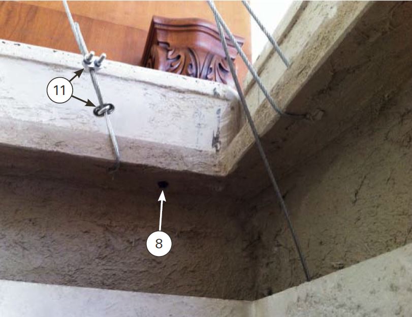 After this is set, you want to fasten mechanically with at least two Tapcons (8), one on either side. Be sure to drill the header from below with a through hole for the Tapcon and use the 3/16-inch masonry drill bit to drill a hole through both the header and molding for a 1/4-inch Tapcon. Overdrill the first hole in the header to 1/4 inch so as to pull the two parts tightly together.
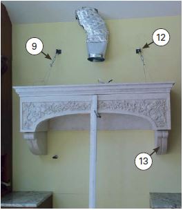
Next you will set the steel tie-back angles (12) above the header within the confines of the breast. There are two smaller 3/8-inch holes that you will use to lag-bolt the angle to the wall and into the blocking. Reference the blocking requirements that were supplied to you in the drawings for the tie-back angle positions and blocking dimensions.
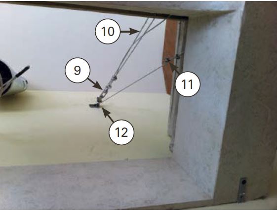
 The 3/16-inch-diameter cable (10) will be used to loop through the turnbuckle (9) that is attached to the tie-back angle (12), and each end of the cable will be attached to the header.
The holes in the header allow you to loop the cable around the flange and use cable clamps (11) to secure loops in the cables. Be sure to use two cable clamps per connection.
The turnbuckle (9) will be used to pull the slack out of the cable and tighten it. Make sure the turnbuckle is adjusted fully extended, and make sure there is enough room for adjustment.
 NOTE: At this point, since many codes require hard piping for the vent fan, you will need to install the vent fan before continuing. The vent fan rests inside the center of the header, upon a fabricated piece of stainless steel that transitions from the opening of the header to the size of the vent fan. This part may also be concrete or even wood with a metal laminate.
The next step before setting the breast is to attach the brackets (13). These two parts get centered on the left and right base platforms of the header. From below you will use a masonry or tile spade bit to countersink the head of two drywall screws (14). Drill through the brackets at an angle so you can set the drywall screws (14) through the bracket into the blocking behind the brackets. These screws may need to be up to 4 inches in length, but 3 inches should be sufficient.
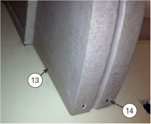 After the screws are set they will need to be covered either with a grout or polyester resin fill similar to those used for repairing natural stone counters. You will also use Tapcons to fasten the top of the brackets to the header.
Dry-set the breast to its position. Be careful to limit the pressure on the front of the header as you place the breast. Mark the top of the breast (16) where it ends on the wall. The vent pipe, if it goes through the top of the breast, needs to be cut into the top flange of the breast. Be careful to keep the cut-out hole as small as necessary to accommodate the vent pipe (15).
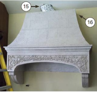 Once you have marked the top of the breast (16), take down the breast and measure the material thickness of the flange of the breast. This thickness may have a little irregularity, but use the thickest measurement. If the edge has a high spot, you can use a 4-inch grinder with a masonry blade to grind the flange, even to accommodate 2-by-4 support blocking to sit flat against the concrete material.
Make a mark below the line you made for the top of the breast. Make it at the measured thickness of the breast flange material minus 1/8 inch. You will put a shim into this gap between the breast and the header, against the wall. This keeps the weight of the breast supported only by the 2-by-4 cleat below the breast flange and against the wall between the header and breast. It ensures no unnecessary weight is transferred to the front edge of the header.
Drill through-holes at the top of the breast flange so that you may put four No. 10 2-inch screws into the 2-by-4 that is now inside the breast to hold it securely in place.
If your design includes a top molding detail, you will use silicone between the breast and molding or use PL Premium adhesive to secure this part in place. Once all of the components are secure, you will use a silicone, siliconized grout or acrylic grout to fill the seams. You can fasten additional 2-by-4 cleats into supplemental blocking on the sides of the breast, and you may also put in additional screws for support which may be patched or filled to conceal them.
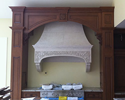
In the first two parts of this How-To series, Jeff Kudrick showed how to design and cast this concrete oven hood. They were published in the February/March and April 2012 issues of Concrete Decor.