
 Decorative concrete precasters have the ability to make a greater variety of products from their one primary material than their stone or solid-surface fabricator counterparts do. The malleability and strength of cementitious composites benefit the cottage manufacturer, allowing them to retain the ability to form infinite custom or semicustom products.
Let’s consider one example here. Rather than the utilitarian mainstay of most interior precast manufacturers, the countertop, we will instead discuss how to design, engineer, fabricate and install a concrete stove hood.

1. IDENTIFYING THE BASIC COMPONENT
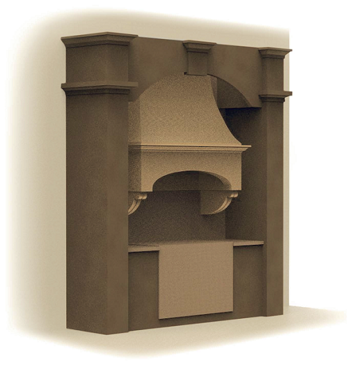
Figure 1 shows the basic components the hood will be designed with.
The moldings (1) are simply transitional components. They can be of varying height and dimensions. They allow for easy fabrication and install.
These moldings can be made using rubber molds that are three pieces — one 8-foot-long run that is square at both ends and two 44-inch long returns that are coped to allow for seamless transitions of the cast material and limitless movement to accomodate any dimension. These are available through Surecrete Design Products or Infinicrete (the company I do product development for), or they can be made in-house with either rubber or PVC.
The largest component is the breast (2). It covers the top of the interior ventilation components and the ductwork. The duct in many areas of the country needs to be rigid, so scheduling the ducts to be installed by another contractor at the same time the hood is being installed is helpful. The ventilation unit would be set by the cabinet-maker, contractor or ventilation technician after the header was installed, and the duct, if it is rigid, would get installed before the breast.
The breast component is best cast and installed as one piece to give the part full integrity. If the look of separate blocks for the breast is desired, maintain a single structural component and grind the joint lines into the breast.
The next and most intricate component is the header (3). This header is the most important component structurally and contains the ventilation components. It is imperative that all considerations and quality fabrication standards are met when casting it. If columns support the header, the weight of the hood rests on the counters and not the header, in which case the header is more stable and does not require cables for support.
The lowermost component in a full wall mount hood design are the brackets (4), which are strictly decorative. Unlike columns, which carry the load of the overall hood to the countertops, the brackets are best suited for a visual and decorative component. These brackets are set with an adhesive and held in place with masonry screws from the inside of the header, plus drywall screws from below the bracket.

2. DESIGNING THE VENTILATION SHAFT AND CHOOSING A UNIT
We have now identified the modular components in a precast hood design and their relative positions. We can start the design process.
The first step in designing a hood is the ventilation unit. The outline can be specified by you, or you can follow the direction of a designer or architect. However, when making products to fit other materials or components, you should understand the basic requirements of said components so that you can serve your clients better and be a knowledgeable resource who can solve problems.
The ventilation unit will be installed, typically, by a suitable contractor who is licensed and insured for this type of work. The flat panel that supports the vent unit is typically provided by and installed with the vent unit by the contractor, although it can also be made out of concrete. It is your job to make the pieces and install them, not to be a jack of all trades. However, this does not nullify your need to understand and educate yourself about the ventilation unit’s installation so you can build products that are user-friendly for the people that specify and install them. Making their jobs easier gets you more work.
When selecting a ventilation unit there are a few basic concerns. The most apparent is the cubic feet per minute (CFM) of air the unit will suck when pulling smoke and grease from the stovetop. The recommended volume is 100 CFM per 10,000 British thermal units (BTU). So a 20,000-BTU burner needs a 200-CFM ventilation unit.
The room size is also a consideration. Think about a room that is 8 feet wide by 10 feet long by 8 feet high, which equals 640 cubic feet of air. The fan will have to move all that air at least 15 times in an hour, so multiply the amount of air (640 cubic feet) by 15 to get a total of 9,600 cubic feet of air moved per hour. CFM is measured in minutes, so divide 9,600 by 60. Your starting point for the range hood’s power is 160 CFM.
Finally measure the stale air in the duct that the range hood will have to overcome. Use values from the Duct Length Adjustment Table (at right, on the facing page) to adjust your measurements for true duct length and figure the CFM needed for your duct.
In our example, we have a simple duct run that is 4 feet of 6-inch straight pipe, a 90-degree elbow, a run of 3 feet of straight pipe and a cap. Adjusted, this becomes: 7 feet of straight pipe, plus 20 feet for the elbow, plus 40 feet for the cap, totaling 67 feet, which translates into 67 CFM.
Add that result to our total CFM (360 CFM plus 67 CFM) to get a calculated CFM rating for your range hood of 427 CFM. In order to be compliant, you would need to install a fan in the range hood that has a rating of at least 430 CFM or greater. (Note: The duct length can be affected by the location of the fan.)
Duct Length Adjustment Table
Smooth metal duct: Actual duct length x 1
Flex aluminum duct: Actual duct length x 1.25 (for 4-inch-wide duct) / Actual duct length x 1.50 (for 6-inch-wide duct)
Insulated flex duct: Actual duct length x 1.50 (for 4-inch-wide duct) / Actual duct length x 2.00 (for 6-inch-wide duct)
Wall caps and roof caps: 30 feet for each cap (for 4-inch-wide duct) / 40 feet for each cap (for 6-inch-wide duct)
Elbows and turns: 15 feet for each (for 4-inch-wide duct) / 20 feet for each (for 6-inch-wide duct)
The hood design allows for a large enough space for most sufficient units. However, oversizing allows for a quieter installation and more productive evacuation of the smoke. An in-line or remote fan unit can be set up separately from the ventilation housing. This housing would contain the stainless hood shroud that would have the controls and the filters. The fan can then be in a separate location, allowing for a unit that moves more CFM and operates more quietly.
Many units do not move the specified amount of air volume, since there are no standards for testing the actual volume of air moved in the final installation.
The capture area of the vent unit is the space that is directly below the vent. The brow of the header is below the space where the vent is set, so the capture space above it inside the filter area allows smoke to be contained until it is vented. The ventilation unit will sit on a piece of trim, either a slab of GFRC with the desired cut-out or a Formica-laminated plywood board. The board typically is finished with a metallic laminate.
Now that you have selected your ventilation unit and have a specified size that you have to allow for, you can design your hood. You should also figure out how the vent will run and sketch it in a drawing.
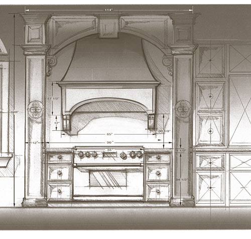
3. SKETCH YOUR HOOD AND ITS DIMENSIONS
By starting with the unit at the desired height and the vent exit through the ceiling or wall, you can sketch your hood around the components. Be sure to locate the cabinets in the drawing as well.
Once the hood is sketched and rough dimensions are figured, you are ready to make your shop drawings for fabrication.

4. BREAK THE HOOD DOWN FOR CASTING ITS PARTS
Now, sketch a 3-D map of the different parts you will cast and assemble for your hood.
The main component, the header, should be fabricated in one piece and allow for bolting into blocking as well as reinforcement embeds for cabling. Enough clearance should be allowed for the lay-up of material.
Your molds may be “multifaceted.” This means the mold comes apart for spraying the face mix and is reassembled so that the entire part is monolithic and strong enough to support itself and the other components.
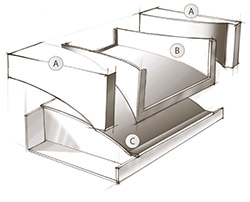
Figures 3 and 4 shows how your pieces fit together.
The Return Panels (A) connect to the Header Face (B). These mold panels are independent so that if the Return Panels have insets or raised reliefs you can demold without damage.

The Brow Knockout (C) sets the arc or relative shape of the bottom of the Header. This attaches to the Header Face and is removable.
The Header Return Panel (D) sets the height of the ventilation unit.
The back corners of the Figure 3 drawing will be identical to the back corner of the cast header pictured in Figure 4. The Side Interior Returns (F) and the Back Interior Return Panel (E) are collapsible and finish the interior of the ventilation unit’s captive area. The back of the header between the Return Panels (A) and the Side Interior Returns (F) will have a foam support insert that will allow the entire back of the header to be a monolithic, fully finished back panel.
Again, Figure 4 shows the back corner of the cast header. (G) is the small panel that is created by inserting the foam to cast the monolithic back panel. The whole back is cast with scrim in two layers connecting Return Panels (A) and (E) the Back Return Panel. The 4-inch return on top of the Header Face (B) is reinforced with scrim. and rebar is embedded in the first 1 1/2 inches of the Header Face return. The rebar can be a lighter, thinner and better-suited bar of basalt rebar (sold by Surecrete Design Products).
The top of the mold face of Header Return Panel (D) (the piece in Figure 3 that sets the height of the ventilation unit) allows the cement to be finished to the edge of it as well as parts (E) and (F).
 5. THE BREAST MOLD
These two diagrams show the breast mold and an exploded view of the mold. The Breast Face Mold (C) can be formed with wiggle board or ribbed plywood and faced with Formica. Using this technique you can make a form that is reusable and modular for the breast. The mold allows for breasts of different widths to be fabricated, and the lower 4-inch extension allows for height adjustments.
At right, the Breast Mold is accompanied by two Breast Return Molds (A). There’s a finished Breast (B) in the drawing too.
The breast mold in the Face Exploded View above starts with the Breast Mold Base Board (M). This is the base upon which you will make your reusable breast mold. The Breast Mold Rib Patterns (K) add reinforcement for the Mold Base Board in the breast’s height dimension and create the shape of the breast. Save the original pattern so that it may be used to make ribs for the breast return molds, which you may or may not choose to make the same.
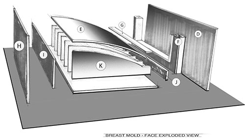
The Breast Mold Bottom Rail (J) and the Breast Mold Top Rail (I) are used to reinforce the Base Board along its length, hold the Rib Patterns square, and create a platform in which to screw the Breast Base Plate (D) and the Breast Top Plate (H). Both of these components have two features, one to hold the Breast Return Molds (A) in place and secure, and may be used as the mold surface to cast upon.
The Breast Base Filler Plate (F) is made of foam or other filler. It is strictly used to adjust the height of the overall piece and may or may noy be necessary in your design. The Breast Mold Transition Face (G) extends the base of the breast so height accommodations can be made. It also creates a perpendicular transition to the lower molding on which it will rest. (Remember figure 1.)
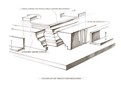
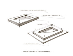
6. THE CROWN MOLDING
The transitional component is the crown molding. It is a separate part that allows you to offer another decorative component without making molds more complex. It also gives you the ability to offer varying details while keeping the whole system consistent. The molds can be made from PVC or rubber or bought from Infincrete.
 |
|
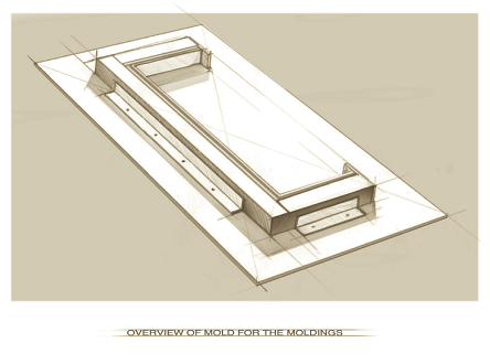
The molds are coped into each other and the longest center mold stays stationary. This allows for any width and depth needed. This part is hand-finished on the inside face and cored with foam so it is lightweight. Aluminum angles make the positioning of the molds to the baseboard square and easily set.
 7. THE DECORATIVE BRACKETS
Now that the main component molds are done, it’s time to tackle the decorative brackets. They can be fabricated in a number of ways, but the quickest is foam, a pattern, router and facing tape. This technique can be used to fabricate a number of shapes and useful items.
Say we want a bracket that is 4 inches wide — then, we are going to cast two 2-inch-wide halves. You start by drawing the shape of the bracket on paper or directly on a piece of 1/4-inch material, typically luan plywood since it is readily available in most shops. If you draw on paper, use contact adhesive to affix it to the pattern plywood. Either way, keep in mind to size the pattern to accommodate the thickness of the router bit because we want the outside of the shape we are drawing.
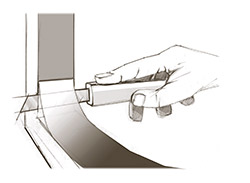 After you have cut a pattern and sanded it smooth you need to fasten it to the foam you will be routing. Two screws will hold it sufficiently. Drill a hole to send the router bit into the foam block. The part can be routed from two halves and assembled with the facing tape. Be sure to carefully rout around the plywood pattern so the foam is clean and smooth. The two opposing halves should be married together to be sure the two cast halves will fit seamlessly when finished. Use fine sandpaper to even out the foam molds if necessary. If you want square edges, they need to be carefully cut with a snap razor or its equivalent, because the router will leave its radius in the edge.
Apply 2-inch facing tape to the interior face of the mold to render a smooth, clean surface.
This set of design and mold layout sequences is the first half of a two-part article. Many details will need to be filled in by the fabricator to allow for a comprehensive design. This information is fairly broad, and many steps are not laid out in elaborate detail.
Much of the skills and understanding necessary to complete this type of project are assumed, and this outline only offers an understanding of the overall process.